Planking the Hull

So begins the arduous process of planking the hull.  The first plank, or Gunwale, is the uppermost plank of the ships hull.  It will define the “run of the ship” or the curvature of hull from bow to stern.  It is important to note that the Gunwale does not follow deck, but instead tends to curve down midship, and then up again as the plank approaches the stern of the vessel, as shown below.

2015-11-07_00004

Since several of the lower decks need to be fitted out on this model, the plank I started with in the above photo probably isn’t technically the Gunwale plank, because there will be others above it as we add the remaining gun decks.  However, its importance is significant in defining the curvature of the planks from bow to stern.

At this point, it is probably a good idea to say something about the method employed for fastening the planks to the bulkheads.  I used yellow carpenters glue and a curved syringe (see one of the later photos).  It is important to not only apply glue to the contact points on the bulkheads but also along the entire edge of the previously glued plank.  This, in my opinion, provides much needed additional support to the planking in general, especially if you have not opted to use any fillers between the bulkheads for the purposes of providing curvature and additional gluing surface.

2016-01-02_00005

You will also notice in my photos that I am using plastic headed thumbtacks to hold the planks in place while the glue dries.  This turns out to be a very effective means of clamping planks to their respective bulkheads.  There are a variety of planking clamping tools out there, and I have not found any of them to be nearly as effective as this approach.

One catch is that you should probably drill small pilot holes to accommodate each pin on each bulkhead prior to gluing your plank in place.  I used a cordless Dremel to drill these holes very rapidly.  Make sure the pilot holes are sufficiently small such that the pins will be very secure when pushing them in after gluing.   The pilot hole is drilled immediately next to the plank and the head of the pin will then hold in the plank while it dries without producing any unsightly nail holes that need to be filled later.  Using disposable pins such as these provides the additional benefit that the pins themselves can be bent as you place them into the pilot holes to accommodate hull curvature.

2016-09-25_00010

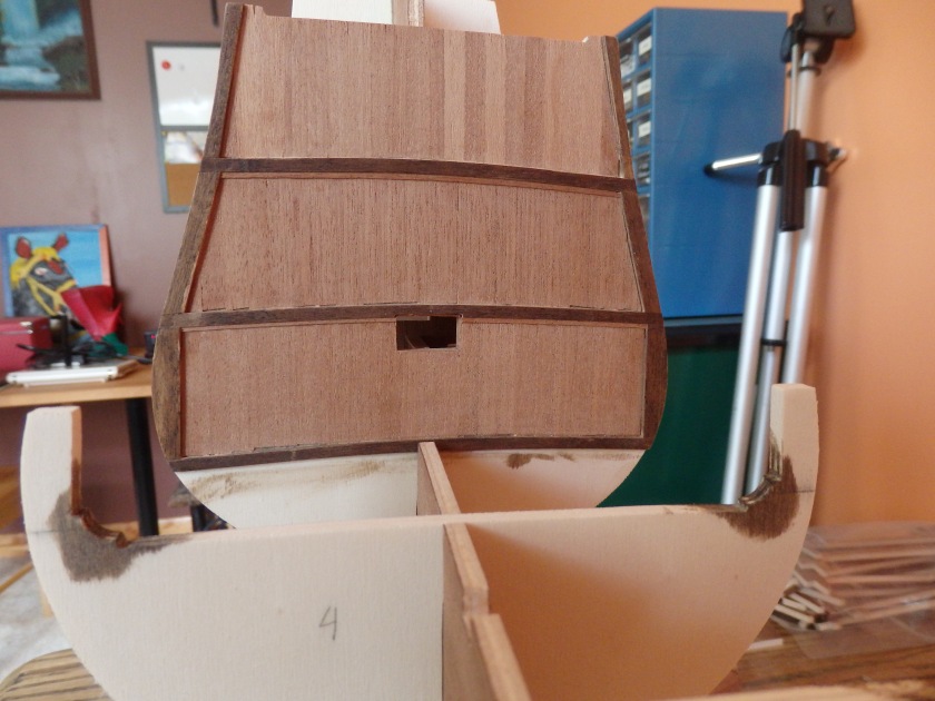
For the bow ends of the planks, I created a bending jig similar to that shown in the above photo.  Since this particular ship does not contain extreme curvature at the bow, nor at the stern (in fact no pre-bending is required at the stern), simply soaking the planks in boiling water for a few minutes, and then clamping them to the above jig and allowing them to dry will produce the needed curvature without the use of a planking iron.

All I did to produce the bending jig was use a french curve to approximately match the curvature of the hull on a piece of scrap wood.  Then, sink several screws at regular intervals along this curve, preferably screws that aren’t threaded near the tops.  Finally, to prevent the screws from digging into the planks, wrap each ones smooth top in electrical tape to provide a padded surface upon which to clamp the planks as they dry.  I was able to bend approximately 6 planks at once using the above jig, 3 side by side at 2 layers deep.  Using the pre-bending jig will easily allow the planks to bend along the curvature of the box as shown.

2016-01-02_00006

You will notice several things about the planking at the bow as shown in this photo.

First, note the fillers that I applied to some of the bulkheads in order to true them up prior to planking.   This can be done by layering and gluing thin wood scraps to the bulkheads at any locations that tend to run low.  Sand the fillers to blends them to the other bulkheads and to the bulkhead to which they are fastened to finish the job.  Of course, any bulkheads that tend to run high can simply be sanded down until the high spot is removed.

Second, note the rabbit between the stem and the bow that provides a nice notch for fitting the plank during the gluing process.  I always begin a plank by fitting it into this rabbit and gluing from bow to stern, as the planks can be left overhanging the stern for this particular ship.

Thirdly, and possibly most important is that the width of the planks at the bow must be tapered.  For this particular ship, in fact, they need to be tapered to about half their original width at the bow.   There is also a span slightly forward of the stern where the planks need to be tapered as well.  The tapering of each plank along the entire length of the hull can be determined by taking strips of paper, or thin wood stock, and measuring the curved length of several bulkheads along the length of the hull.  The length to be measured should be the distance between the keel, and the Gunwale plank about every 2 to 3 bulkheads, depending on the degree of change you are trying to capture.  Once you have these lengths, take the longest length that occurs mid-ship, and divide it by the width of your planking material.  This will give you the number of planks you will need to cover the span.  Then, at bulkheads where the length is less than this maximum, divide each length by this number of planks you determined in the previous step to determine the approximate width that each plank needs to be at each bulkhead.  You will then find you have a rough template for sanding off the width of the planks.  Note that the distance at the stern will actually be greater than at mid-ship, requiring the addition of “stealers”, or additional short planks to make up for this additional distance at the stern.

2016-02-14_00007

I found that a belt sander works very nicely for sanding a continuous curvature into each plank.  In fact, before I even pre-bend my planks using the jig described earlier, I will taper the planks to their necessary width at the bow end by applying a stack of them to a running belt sander, and applying pressure to the stack using a scrap piece of wood.  This gets you the bulk of the tapering for the bow, prior to even bending the plank.  Then once the planks are ready to be placed, I will fine-tune their curvature by smoothly running the edge of the plank along the curved edge of the belt sander.  You should also taper the edges of each plank inward the tiniest bit along their entire length, as this will guarantee a tight fit against each other on the hull.

Once a few planks had been fastened along the Gunwale plank, I moved to the keel and placed the Garboard plank along with a few others alongside it.  There isn’t too much special to say about the Garboard plank except that it will possibly require a little additional sanding in order to get its edge to fit in the rabbit between the keel and the bulkheads.

2016-02-14_00008

You will likely find that “stealers” will be needed at the stern as shown in the photo above.  Stealers should typically be tapered to about 2/3 their width at the bow end, and they should maintain their full width at the stern end.  I typically notch out the preceding plank 2 to 3 bulkheads in from the stern, prior to even gluing this plank to the hull.  Then, I will add the tapered stealer, and the next plank can again be notched to accommodate the end of the stealer.  Throughout all of this, avoid removing any width at the stern-most end of the planks because recall that the goal here is to cover a larger distance by adding the stealer in the first place.

2016-09-11_00009

In combination with the push pins, a good set of clamps is a must for the task of planking.  As you can see in the above photo, I tend to place one clamp at the mid-point between each bulkhead and gluing a plank in place.  This ensures a tight fit against the plank immediately preceding the one being glued.  Larger clamps can be used for uncooperative plank ends such as at the stern where a pretty decent twist is required.

2016-09-28_00011

Eventually, your “strake” or group of planks will become too wide for your clamps.  When this happens, just skip a plank to create a gap.  Even better, this plank that you skip – shape it ahead of time and use it to glue the first plank of the next strake.  You can ensure that it doesn’t accidentally become fastened to the bulkheads by laying little strips of wax paper between it, and the bulkheads and first plank of the next strake.  Then when the first plank of the next strake is dried in place, this plank can be removed and you have a perfect gap for applying your clamps as shown in the photo.  Just be sure and mark the planks that you removed so you have it for later.

2017-03-18_00012

Several strakes can be completed in just this manner, leaving you with only a couple gaps to fill in later.  When it is finally time to place these final planks, you will find that your pins are useless under this scenario.  So, take several plank scraps and sand them down to a very fine point that their end.  Then, do any final shaping to your gap-filler plank so that it fits in the space you created previously.  When it comes time to glue it in place, use the sharpened scraps as wedges to secure the plank in place while it dries (see photo below).

2017-03-19_00013

When you are though, you may find that time and humidity, or even a few mistakes along the way, have resulted in some gaps between some of your planks.  To remedy this, I would recommend sanding some plank scraps down to very thin width and inserting them into these gaps to fill them as opposed to using wood fillers.  This will result in relatively invisible repairs to any imperfections that remain.  Once you sand down the hull, you can repeat this process for any additional gaps that may appear during this process.

2016-11-20_00072

I’m fairly satisfied with the end result of this technique, and I look forward to providing updates in the future as I move toward fitting out the lower gun decks.

Stem, Deck, and Stern

Following the careful adjustment of the deck slots for the right-angle positioning of each bulkhead, I proceeded to stain the visible parts of each bulkhead dark brown.   Then, I glued each bulkhead in to place one at a time using the deck sections and other bulkheads to hold everything in position.

Bulkheads glued into place and visible areas stained dark brown.

You can clearly see strong warping in the false keel below, but this will be taken out later by the lower decks as they are glued in place.

Next, I glued together the stern assembly from the 2 bulkheads and false deck, which until this point had been simply dry fitted in place.

OLYMPUS DIGITAL CAMERA
Constructing the stern assembly.

Since portions of the interior might be visible through the rudder tiller opening, I opted to finished these interior surfaces using some thin laminate stock I had left over previously from my HMS Victory project.

OLYMPUS DIGITAL CAMERA
View of finished interior.

Note in the above photo, the fore-side of the furthest aft bulkhead is finished with the laminate board as well.  I stained the underside of the false deck piece to further ensure that any visible surfaces would appear as part of the true ship’s interior.

OLYMPUS DIGITAL CAMERA
Finished fore-side of stern assembly with deck beams in place.

Now that the stern assembly was in place, I could proceed to glue down the lower decks.   I started with the foremost section, carefully using a combination of T-pins and clamps to press the deck firmly against the bulkheads.

Pinning the gluing the fore-lower deck in place.

There was no need to worry about any bulkheads beyond those in contact with this first section of the deck.  In other words, the warping of the false keel would ultimately be corrected most by positioning each section of deck firmly against the next.

Pinning the gluing the remaining lower deck pieces in place.

You can see in the above photo that I drilled holes in the sections of the deck near their adjoining locations so that clamps could be used to “true-up” the false keel.  At this point, most all of the warping of the false keel has been removed.  The only warping that remains is along the bottom-most portion of the keel.  this will be corrected later by the positioning of the actual keel.

As it happened, following its construction, there was a severe twist in the stern assembly.  To correct for this, I cut the stern assembly straight down the middle as shown below so that the twist could be removed.

2015-07-15_00002
Stern assembly cut to remove twist.

Then, I was able to re-glue the rear of the assembly to correct the twist that had been introduced during the first pass of construction.  You can see the slight mismatch between the two stern sections in the photo below.  This won’t ultimately be visible at all in the final model.

View of re-attached stern assembly to remove twist.

You can also see in the above photo the tapering of the false keel toward the stern.  I added this so as to create a rabbit joint for the hull’s planking to come later.

Bow fill in pieces and rabbit joint stock added for future planking.

I added a piece of stock to the bottom of the false keel to create this rabbit joint.  Likewise, I added a strip to the bow as well following placement and sanding of the fill-in piece along the length of the bow.  From the above two photos, you can easily imagine how the stem and keel will be placed, leaving a notch perfectly sized notch to accommodate the ends of the hull’s planks.

Next, I finished the aft portion of the stern using stock provided with the model in “herring-bone fashion” as described in the kit’s instructions.

Finishing the stern using the stock provided in “herring-bone fashion”.

Moving on to the stem, I began by carving and shaping its various features as indicated in the plans provided.  I started with the recessed region to accommodate the gammoning of the bowsprit to come later.


Carving a recessed region in the stem to accommodate future gammoning.

There is also a taper toward the fore-end of the stem.  However, the most difficult part of the process was shaping the curvature of the stem to match the curvature of the false keel.  A proper fit would help ensure a strong glue joint between the stem and false keel later, as shown in the photo.

The finished stem attached to the false keel. Note the rabbit joint is now visible.

The rabbit joint between the keel and the stem is now visible.  This is not part of the kit’s plans, but an addition I made to specifically ease the planking process later.

Next, it was time to attach the keel.  First, I added reinforcement blocks to accommodate the screws that would later be used to attach the model to its display stand.   This is an easy step to forget, but very important to ensure a strong ship-to-stand connection later on.

The remaining keel warping is evident here.

You can also see the false keel is still a bit warped toward the bottom of the ship.  To fix this, I rigged up a straight edge placed in the rabbit joint I created between the false keel and the soon-to-be-placed keel.  This straight edge would allow me to clamp out any remaining warping in the keel.

Keel glued in place and warping removed!

Finally, the keel was glued in place using a combination of clamps, and the two future stand screws, which were certainly helpful during the gluing processes.

At this point, we are about ready to begin the long and arduous process of planking!

Bulkheads and Deck Preparation

I began this project by first marking out the positioning of the two gun ports and tiller port on bulkhead #1.  Sizing and positioning were based on the scale plans provided.

Gun ports and tiller port marked and cut from bulkhead #1.

Since this was relatively thick plywood materials, I pre-drilled holes at all port corners, then rough cut the openings using a small saw.  Final shaping was accomplished using a combination of sandpaper and filing.

Ports also needed cut from the curved bow filler piece as shown.  These were a bit tougher to mark out as you can imagine given the curvature of this piece.  I positioned their height based on the heights of the gun ports in the hull plans provided.

Bow filler ports and window cutouts.

For some reason, several of the windows were not pre-cut from the pre-fabbed wall pieces, so I went ahead and cut these out as well, just to get them out of the way.

While I was in cutting, drilling, and sawing mode, I went ahead and marked out the details of the stem.  I went ahead and cut the slot needed for the gammoning to come much later in the project.

OLYMPUS DIGITAL CAMERA
Marking out the stem.

With the major cutting complete, I went ahead and sanded the slots for the bulkheads and frame so that each fit easily into position, and aligned with the deck.  There was substantial warping present, especially in the main frame.  I’ll address this later.

Bulkheads sanded and dry fit to the frame.

Speaking of warping, bulkhead #1 – the one with the gun port cutouts shown below was substantially warped as well.  I found that steam ironing it using a standard clothes iron helped substantially.  Any remaining warping can be addressed when I attached it to the framing.  I spent substantial time sanding and adjusting each of the bulkheads along with the framing pieces so that everything fit together comfortably.

Fitting the stern bulkheads and framing pieces.

With the bulkheads in place, the pre-fabricated decking plywood needed sanded to accommodate each of the bulkheads.  I realized that if I did this carefully, I could use the deck pieces to correct the warping present in the main frame.

OLYMPUS DIGITAL CAMERA
Dry fitting the deck and bow filler.

This being the case, I very carefully began sanding the slots in the first deck piece to accommodate each of the bulkheads, working from bow to stern.  At the completion of the first deck piece, I was able to adjust the bow filler pieces for dry fitting.

An inside view of the first deck piece and bow filler.

With each deck piece properly sanded to accommodate the bulkheads, the main frame was gradually forced straight.  In the end, sighting down the length of the frame revealed very little remaining warp.  Any warp remaining can be fine tuned using filler pieces between the bulkheads.

All lower deck pieces sanded and dry-fitted.

It is extremely important that the main frame be made as straight as possible before planking the hull.  Luckily, the deck pieces assisted me in what would normally have been accomplished using filler pieces between the bulkheads.  As I sanded the slots in the deck pieces, I was careful to measure the distance between the bulkheads at the main frame.  Then, when widening the slots in the deck pieces, I propagated these same measurements down each side of the hull to continually ensure that each of the bulkheads were parallel to one another, and perpendicular to the frame.


HMS Victory Revisited

Before I dig too far into this next build, I thought now might be a great opportunity to give a quick recap of my recently completed  (2012) HMS Victory build.

OLYMPUS DIGITAL CAMERA

This build was based on Constructo’s 1:95 scale model.  Constructo is another European company that produces its kits in a style emphasizing natural wood tones and brass highlights.  This was one of the things that drew me to this particular kit.

OLYMPUS DIGITAL CAMERA

Unfortunately however, there was a lot of work that had to be done to create a more realistic model of the Victory.  For example, I reworked all of the stern and quarter galleries with more realistic window panes.

OLYMPUS DIGITAL CAMERA

I also did a lot of work on deck to produce better scale representations of the various fittings throughout.

OLYMPUS DIGITAL CAMERA

Note the signal flag lockers I added on the poop deck.

OLYMPUS DIGITAL CAMERA

There were no ships boats included with the kit, so I was lucky to be able to find pre-fabricated ships boats that very closely resemble the various sizes of boats stowed on the Victory.  To these I added my own framing touches to the extent that I was able.

OLYMPUS DIGITAL CAMERA

I hand painted my own flags using a heavier card stock that could be formed into a wavy pattern.

OLYMPUS DIGITAL CAMERA

Changes to the rigging was the most significant change.  In fact, I all but ignored the rigging plans provided with the kit and instead opted to utilize the various HMS Victory resources available to reproduce her rigging much truer to the original.

OLYMPUS DIGITAL CAMERA

I purchased many different sizes of rigging line to honor the various scales of rope that would have been used on the real ship.

OLYMPUS DIGITAL CAMERA

In the end, I am very pleased with how it turned out. My build log for this model (albeit incomplete) can be found at http://hmsvictorymodel2004.blogspot.com/.  This post officially completes that build log.

Anyone who happens upon this post and might be interested in purchasing this model, please feel free to contact me.  While I do not have a firm price established at this point, I definitely need to make room for my next build – the Wappen.

Preparations

Preparing for the long journey ahead…

Today marks the beginning of what will likely be a multi-year journey building the Wappen von Hamburg.  This ship was built between 1667 and 1669 as a convoy ship to protect German Empire merchant vessels from pirates.  There were actually a series of three ships built under this name, the subject of this build log being the first in the series.  This particularly ship was lavishly adorned with numerous carvings, making it a unique build.  The Wappen von Hamburg was tragically destroyed by fire in 1683 killing many of the crew and soldiers aboard.  For additional information on the history of the Wappen, as well as some really nice photos of a scratch built model, check out this website.

The model I will be building here is Corel’s 1:40 scale model. Its finished length is 43 inches and its height is 36″.  This is an extremely high quality kit. However, as with many European kits, the instructions are very limited in scope, and the plans must be studied very carefully to ensure that each build step is thoroughly understood to prevent “painting oneself into a corner” so to speak.

Here is a series of photos documenting the contents of the kit:

OLYMPUS DIGITAL CAMERA
Wood strip stock is predominantly walnut.
OLYMPUS DIGITAL CAMERA
Bulkheads and other pre-fabricated pieces.
OLYMPUS DIGITAL CAMERA
Silk flags, sail material, and decking.
OLYMPUS DIGITAL CAMERA
Cannon assemblies, blocks, and various other small fittings.
OLYMPUS DIGITAL CAMERA
Pre-cast figures and lanterns.
OLYMPUS DIGITAL CAMERA
Laser etched window frames, gunport hinges, etc.

Before beginning, I tried to take stock of all kit components, as well as develop a cutting schedule for the wood strips provided.  This was a time consuming process as most of the referencing had to be done from the plans.  Here is a copy of the cutting schedule in an Excel spreadsheet for anyone who might find it useful.  I found that there seem to be several strips missing from the kit.  I’ll probably have to order these later once I have a better feel for what is needed.  No big deal though, walnut strip can be ordered from Model-Expo.